Symbio designs the new Mobiris control center for Brussels Mobility
The mission consists in designing a new Mobiris control center for Brussels Mobility, in a predefined architectural space, located in the same building as the future one for STIB, another Brussels company. STIB is responsible for the transportation of passengers by metro, streetcar and bus and will have to be able to work in close collaboration with Mobiris.
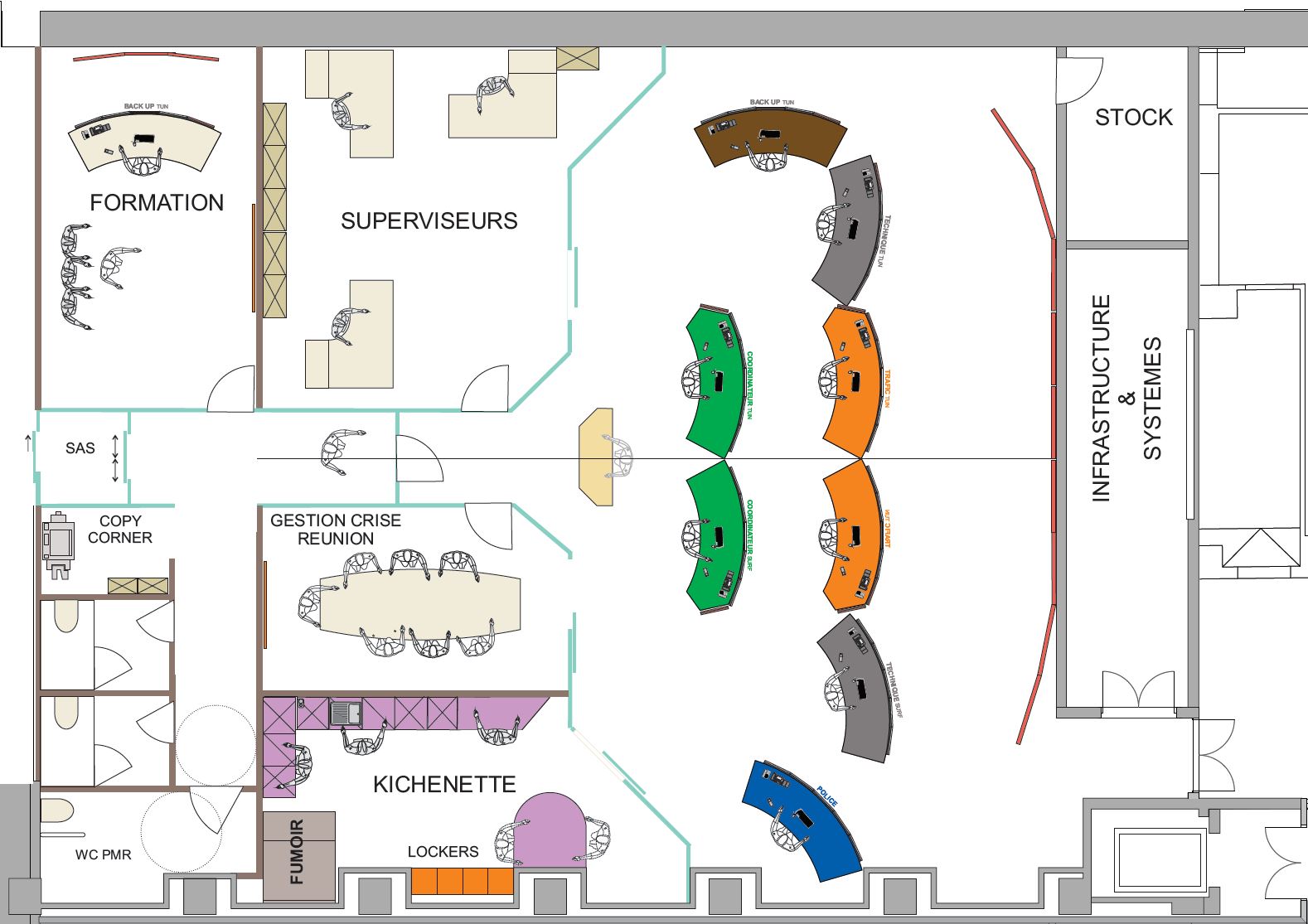
The future Mobiris room should be able to accommodate up to 8 workstations, as well as a series of secondary rooms such as a supervision room, a crisis room, a kitchenette and a training room.
The mission was carried out as a subcontractor of our partner Namahn, with whom we were already carrying the design the STIB room.
Challenges
We had to meet the three following main challenges:
- Fitting the workstations and secondary rooms in the available architectural space, taking into account future evolutions, with 2 presumed phases: one starting in 2019 and a second one, with additional workstations, in 2026.
- Inserting the videowall, with its particular geometry, in the space available under the ceiling
- Ensuring the best possible interaction with STIB, whose new control room will be located on the same floor. Ideally, the two rooms would have been annexed, or even integrated, but the architecture of the building did not allow it.
The mission was achieved in 2 phases.
Phase 1 - Initial design (2017-2019)
Requirements analysis
The first step of the project was analysis of the requirements, focusing on future needs rather than existing ones, and addressing questions such as:
- How many operators and workstations will there be
- What information should be provided specifically on each workstation
- What information should be presented on the videowall and who should see it
- What interactions, both verbal and non-verbal, will be necessary between the work positions
- Should there be secondary facilities, such as a kitchenette, a crisis room, an office for a supervisor, etc.?
- What are the vision requirements on the work positions and the videowall from these secondary rooms
- Should there be a strong coupling with the STIB room next door and how can this be supported?
Constraints analysis
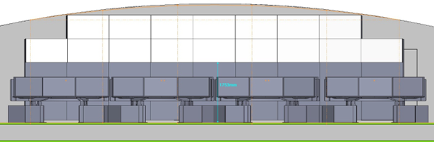
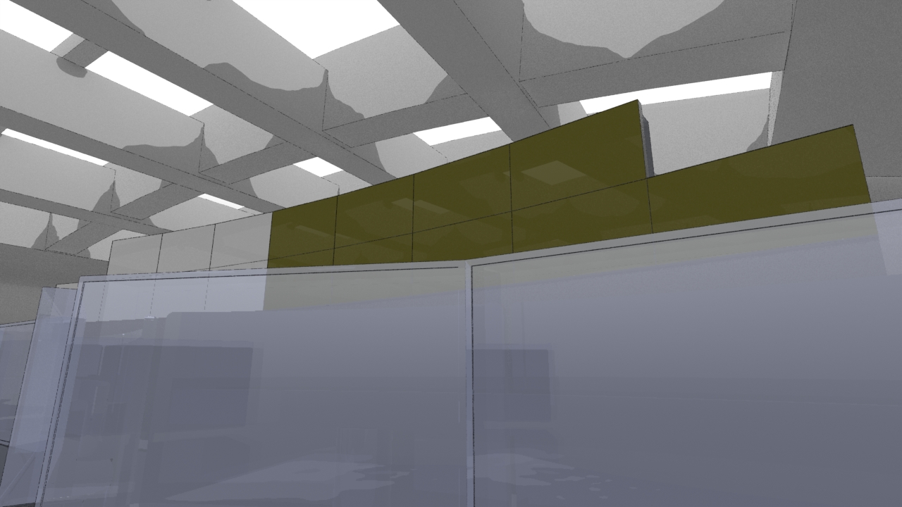
The main constraints are architectural. And in particular related to the particular shape, a vault, of the ceiling of the future room.
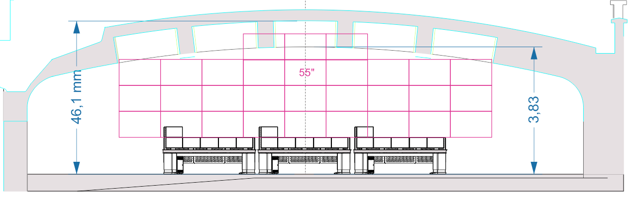
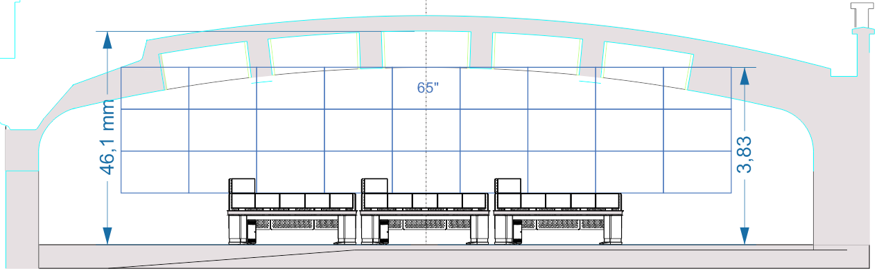
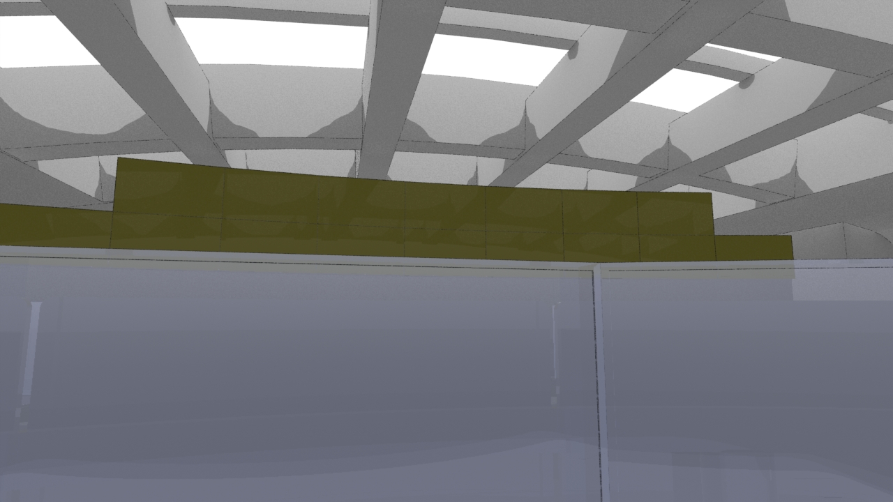
Indeed, the room will have to provide a videowall, of consequent size, and it will therefore have to fit, with its particular geometry, into the space available under the ceiling. For example here are below two evaluations of presumed layouts for the videowall, based on 55" and 65" screens respectively. It is clear in both cases that they physically conflict with the ceiling.
 |
 |
Console study
The first step was to choose the console to be used to install the operators. Knowing the console, and in particular its consumption of floor space, is decisive for the study of the layout of the room.
It was quickly decided to use the same console as in the future STIB room, the two projects being associated.
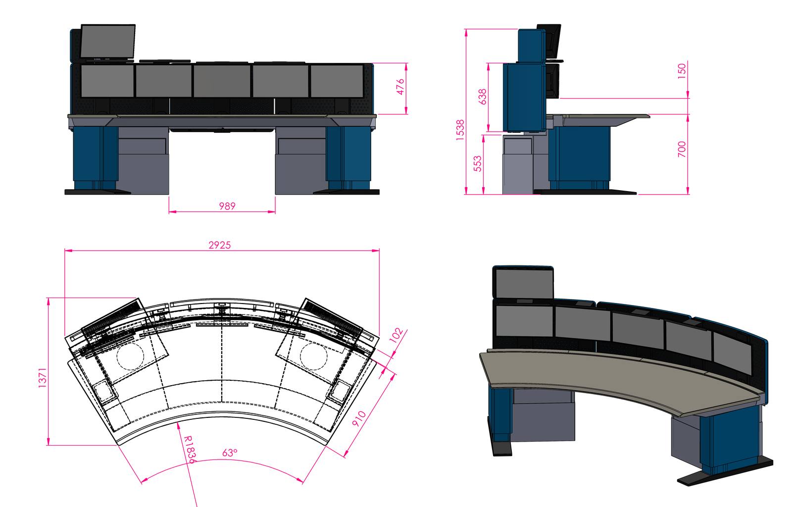
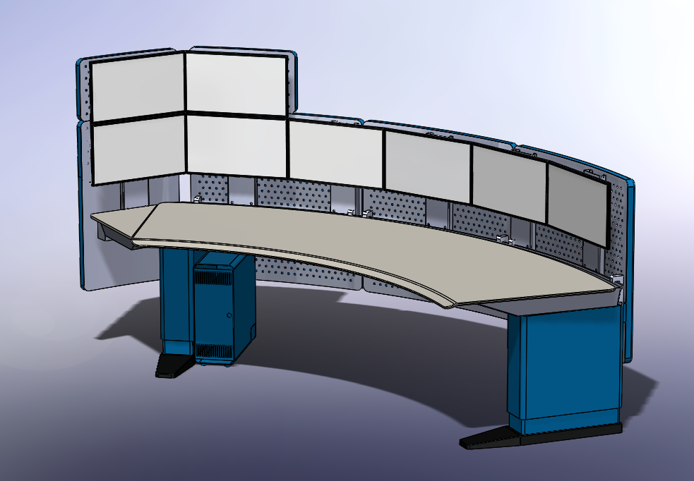
This console should then receive one or two extensions, allowing Mobiris to install additional screens, for example 2 on the left side in the following figure.
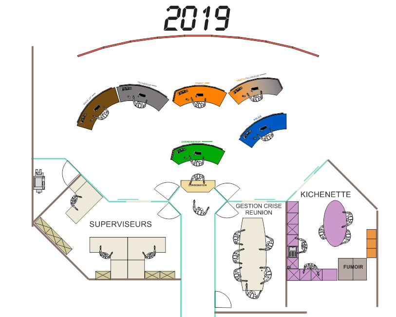
Room layout
The working group formed with Mobiris then studied different versions of the room layout that could be fit in the available architectural space. A tentative layout was selected, and specified in two versions. An initial version planned for the start of operations in 2019 and a version covering future needs, in 2026.
 |
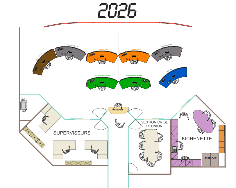 |
The study of the layout, until then focused on the purely operational area, was then extended to the entire space available in the architecture, to accommodate additional rooms, such as a training room, a copy corner and sanitary facilities.
Study of the videowall
The detailed study of the videowall then began. The design of the videowall must be a compromise between the display of information, in sufficient quantity and visible by the operators who have to perceive it, and the limitations of the architecture, in particular the arched structure of the ceiling.
Different versions have been studied, varying the size of the basic screens (46" or 55"), the geometry of the screen grid and the distribution of the images presented on the different screens.
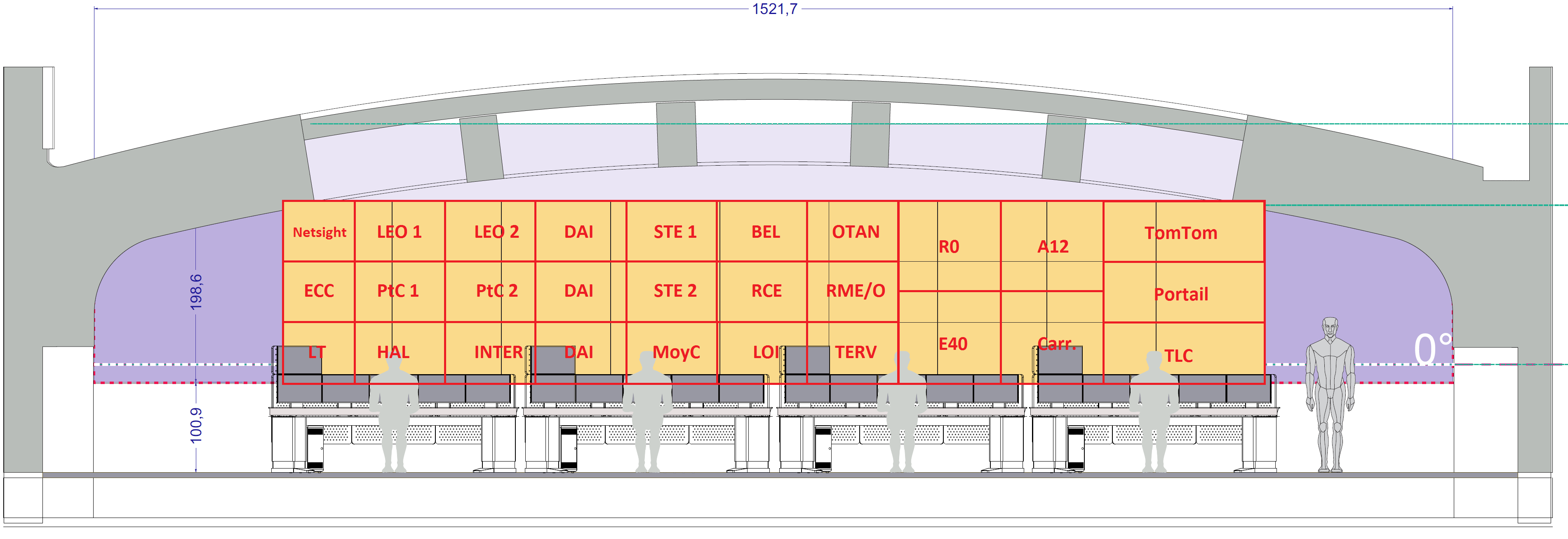 |
 |
3D modelling and positioning of the videowall
The room and the entire Mobiris space, including the annexes, were then modeled in 3D.
Validation of fields of view and of interactions within SymView
The 3D model of the room was then ported to Symbio's SymView exploration and validation environment to verify that the operational requirements previously defined were met. In particular visual information taking on the videowall from the work positions and the visual interactions needed between them. We mostly wanted to verify that there were no visual obstructions impeding these requirements
Two videowall options (geometry of the screen grid) were also available in SymView, to allow a better appreciation "in situ" of the 2 options.
The work was done in both VR and PC versions of SymView. Both applications were provided to Mobiris to choose the preferred videowall configuration and formally validate the room.
The final videowall configuration was chosen and no harmful visual obstruction was detected.
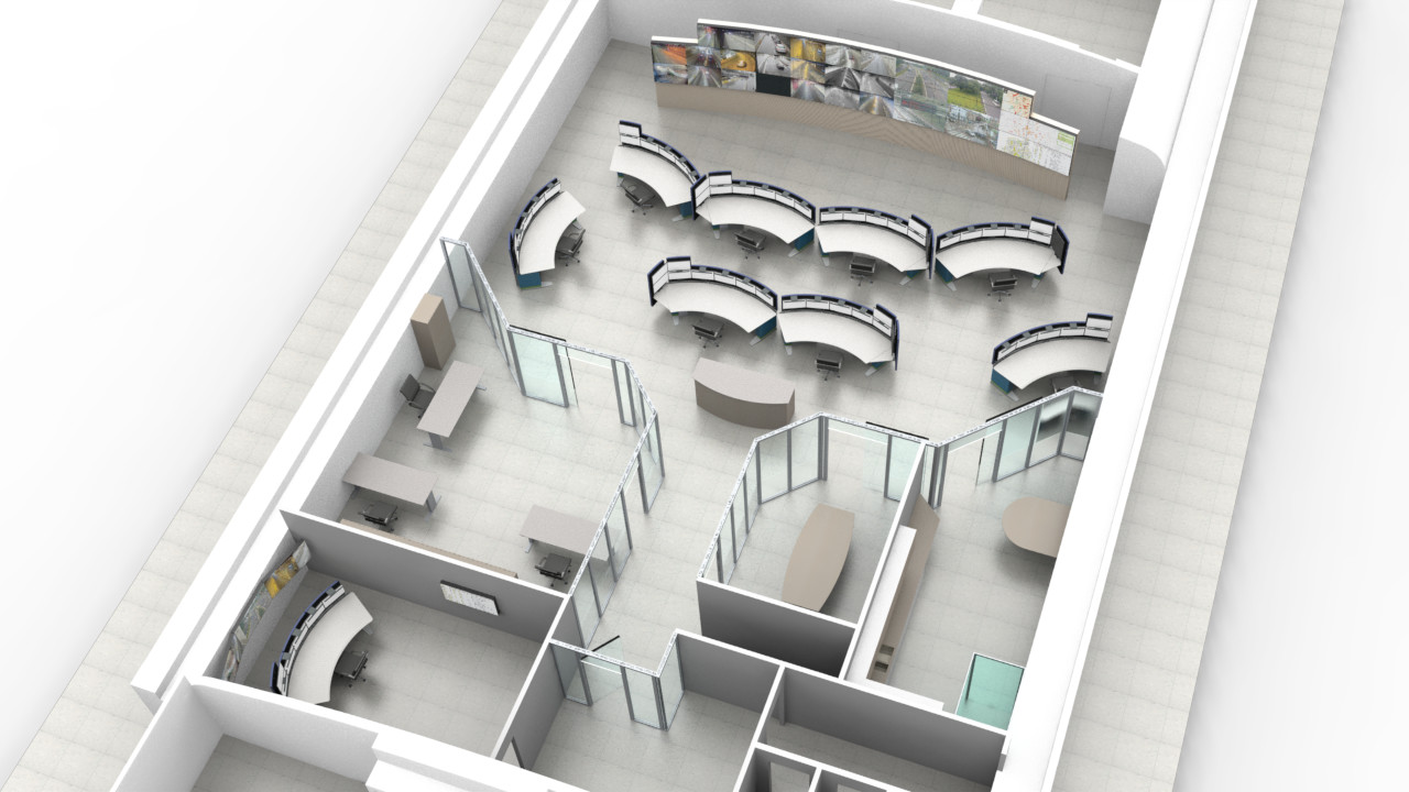
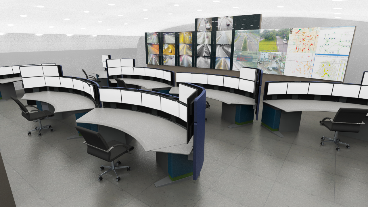
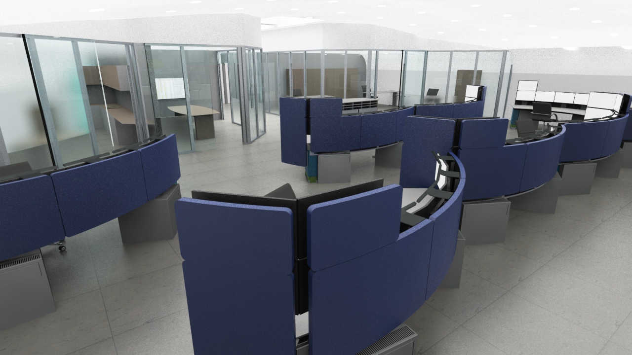
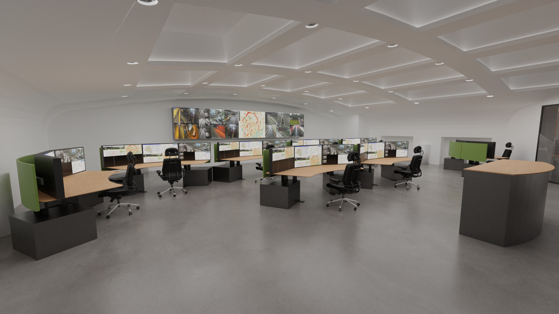
3D renderings
With the room now complete, Symbio produced 3D renderings for Mobiris' internal and external communication.
 |
 |
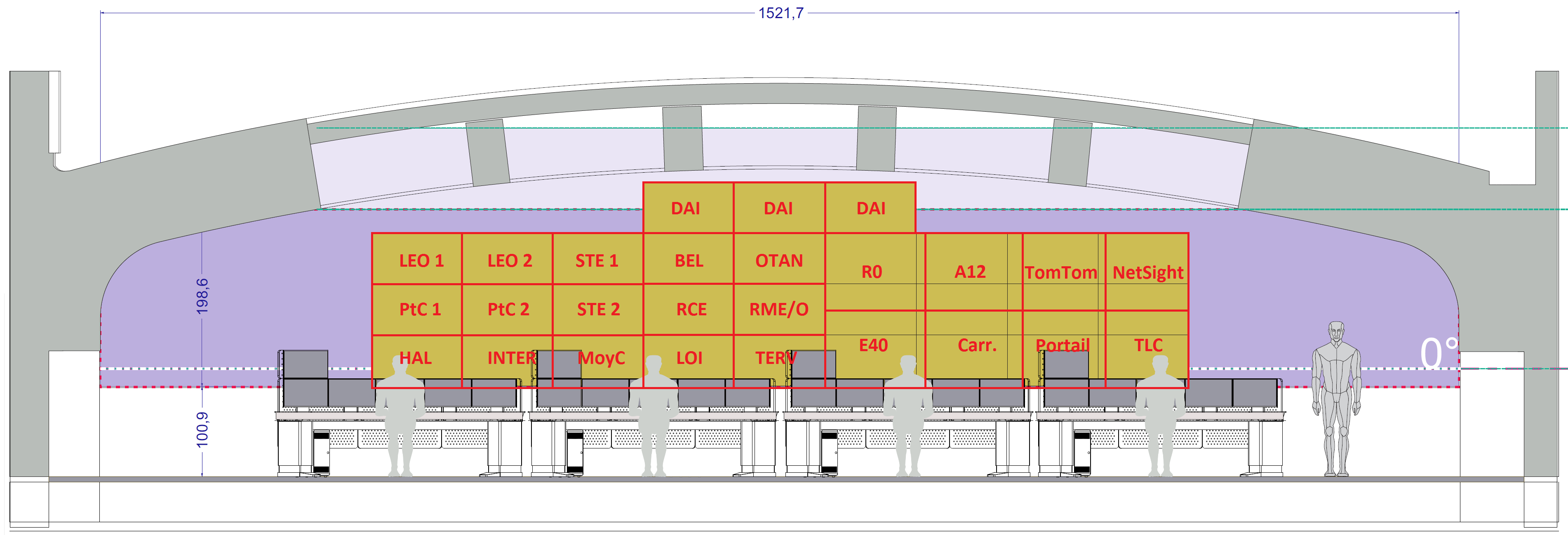
Phase 2 - revision of the design (2019-2020)
Some time after the Phase 1 study, Mobiris revised the initial hypothesis concerning the size of the screens placed on the workstations. Initially planned as 24", they were replaced by 43" Ultra HD 4K screens to better integrate the applications to be provided on the different workstations.
Mobiris therefore asked Symbio to evaluate this new working hypothesis and in particular its impact on the visibility of the videowall from the workstations in the previously established room configuration. And if necessary, in case of obvious visual obstruction, to propose solutions for resizing and rearranging the videowall to optimize access to this remote information.
The 3D model of the room produced during Phase 1 has therefore been updated with this new hypothesis. Since the lowest portion of the videowall in Phase 1 (lower 3rd row) could no longer be seen due to the visual occlusion of the 43" screens, the geometry of the videowall had to be revised as follows.
This new configuration was used as the basis for external evaluations.
Target user population
Impact studies were then conducted. They were carried out for two user ranges of the Belgian population:
- Percentile 5 of the female population: short people, 153.4cm, with eye height at 110.8cm.
- Percentile 50 of the mixed male-female population: average people, 170.6cm, with eye height at 122.8cm.
The 95 percentile of the male population (very tall people) that Symbio typically incorporates into its studies was not studied because it was clear that these people would not be impacted by the change in screens size.
Visibility study
Vision simulations with the now higher row of displays on the desks for the different positions and the two percentiles of the population considered were performed. With sometimes the observation (left figure) that for the frontal positions and the 5th percentile of the female population (height 153.4cm, eye level at 110.8cm) visual occlusions were unavoidable. For the two rear positions the videowall could not be perceived either (right figure), including for the taller mixed 50 percentile (height 170.6cm, eye level 122.8cm).
 |
 |
The conclusions of the visibility study are therefore as follows:
- Front positions: visibility of the videowall is acceptable for the 50 percentile of the mixed population for front-end positions. Visibility of the videowall is not acceptable for the 5 percentile of the female population from the front stations, but it can be met by adjusting the height of the chair, sometimes significantly.
- Rear positions: visibility of the videowall from the rear stations is never possible. It is advisable to give up the need of vision of the synoptic for these two remote posts and to provide complementary means of visualization on the local screens.
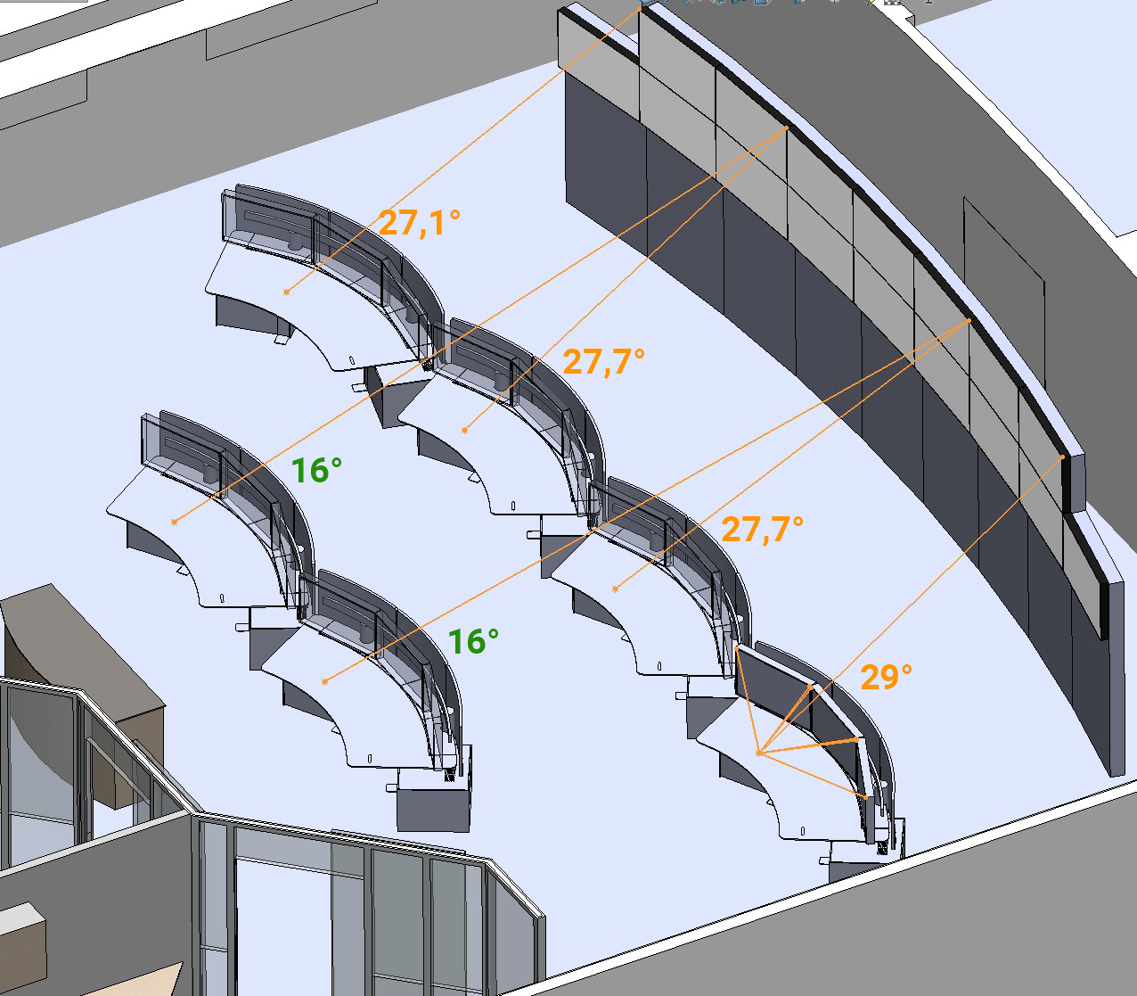
Neck angle study
The neck angles are the angles that the neck must take to perceive elements, here screens, located above the eyes plane. The standards and the medical literature do not provide clearly defined thresholds of acceptability for these angles. Our practice and the reading of the literature led us to consider as acceptable a neck angle between 0° and 25° for regular upward viewing actions and from 25° to 35° for rare and unsustained viewing actions. Any value greater than 35° is unacceptable in all cases.
The following figures show neck angles for the different positions for the 5 percentile of the female population (left figure) and for the 50 percentile of the mixed population (right figure).
 |
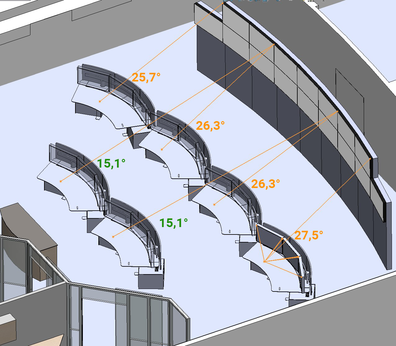 |
In both cases the neck angles for the front row positions are slightly higher than the 25° value but this is considered acceptable because the information on the videowall is not permanently attended. The neck angles for the rear positions are largely acceptable.
3D model update
After receiving the study report on the two previous points, Mobiris asked us to simplify the implementation of the videowall and to limit its lateral extension. The 3D model of the room has been adapted accordingly.
SymView VR & PC new versions and new 3D renderings
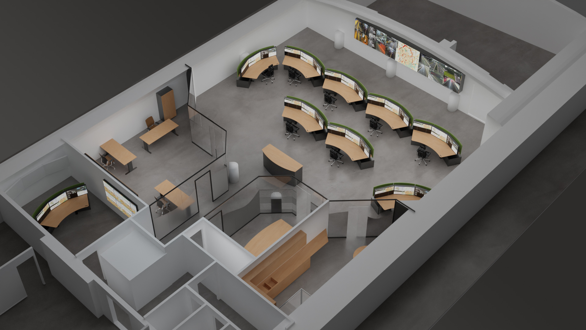
Two new versions of SymView VR and PC software were produced to allow exploration of the new room configuration. A series of new high quality 3D renderings were also produced.
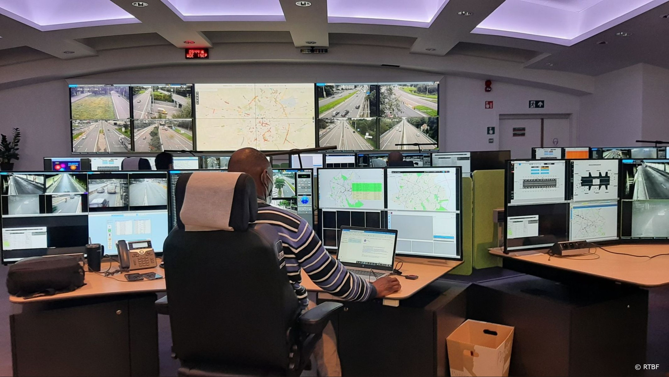
Below is the room once completed and in operation.
Share this: